Friday, June 14, 2013
Wednesday, May 22, 2013


Oscilloscope 101
An OS (Oscilloscope) is a device used to display time varying signals such as AC signals as well as DC with some impedance such as a Capacitor, which ultimately helps us make measurements.
We first begin this lab by connecting our Function generator to the OS with a "Sinusoid" signal output at a frequency of 5kHz and a Peak Voltage of 5V.


Sinusoid Signal Output
Period: 0.208ms
Peak-to-Peak Amplitude: 5V
Zero-to-Peak: 2.25V
RMS Value: 1.77 Volts

DC Offset Signal
Mystery Signal!!!!
DC Voltage: 0.5-7.5v
Frequency: 7Hz
Peak-to-Peak Amplitude: 1V-1.25V

Mystery Signal


Wednesday, April 10, 2013
Operational Amplifier Lab 1
The operational amplifier lab looks at, well... operational amplifiers! As always is the case, we look at a specific kind of circuit element for which we wish to analyze. Today, we look at an LM 741 Operational Amplifier.

There are a wide range of Op-Amps that do something, this one inverts the voltage!

There are a wide range of Op-Amps that do something, this one inverts the voltage!
Monday, March 18, 2013
Tansister Switching
In this lab, we examine the properties of a Transistor as a circuit element. We particularly examine an NPN 2N3904 type of transistor due to how common of a part it is.
.jpg)

A2 is a Green LED which we use as an indicator (Power) for the amount of current the transistor lets through.
This video shows my fingers replacing the R2 resister and acts as a switch:
.jpg)
.jpg)
The Transistor essentially acts as a resistor due to its internal chemistry.
The Following Diagram shows the lab set up of our circuit.

A2 is a Green LED which we use as an indicator (Power) for the amount of current the transistor lets through.
This video shows my fingers replacing the R2 resister and acts as a switch:
After putting on a small light show, we no reintroduce that R2 where my fingers where and started collecting of current flowing through A1 and the Green LED.
R1 = 39.5 Ohm R2 and R4 = 10kOhms R2 = 39Oms P1 is a Linear Potentiometer
Using MATLab
MatLab is an engineering program used to solve complex systems. In this particular lab, we used the Matrix function of MatLab to solve a system of equations to find the 2 mesh currents in the circuit:
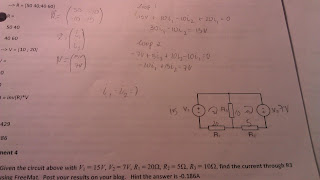
Once I chose the mesh current directions, I solved a simple system of equation which I then wrote into a matrix. Using the MAGIC of MatLab, I plugged the matrix into the program to solve for the mesh currents needed to find the voltage drop through the 10Ohm resister (parallel to the two voltage supplies).


Once I chose the mesh current directions, I solved a simple system of equation which I then wrote into a matrix. Using the MAGIC of MatLab, I plugged the matrix into the program to solve for the mesh currents needed to find the voltage drop through the 10Ohm resister (parallel to the two voltage supplies).

Sunday, March 17, 2013
Lab 1: Using a Multimeter
Objective: The objective of this lab is to familiarize ones self with the tools of a circuit analysis laboratory, namely the use of a Digital Multimeter.

Procedures
- Resistance Test
- Voltage Test on DC Power Supply
- Measuring Voltage Across an LED
Resistance Test: Measure resistance for various resistors, (note colour bands).
Brn, Grn, Brn, Gld 150 Ohms %5 tol 149.0 OhmsResistor Colours Value from Colours Measured Values
Orng, Blk, Blk, Gld 30 Ohms %5 tol 30.0 Ohms
Orng, Blk, Blk, Gld 30 Ohms %5 tol 30.2 Ohms
Ylw, Prpl, Ylw, Gld 470kOhms %5 tol .475MOhms
Voltage Test: Measure the Voltage on 9V DC Power Supply/Measure Voltage Drop across 150Ohm Resister.
Value: 9.03V
Voltage Drop across 150Ohm Resister

Measuring Voltage Across LED: Construct circuit from figure in Lab Manual (see picture below), and measure the voltage across Green LED in series with a 150Ohm Resistor and a 5V Power Supply. (actual voltage supply as measured was 4.5Volts)

Values:
Voltage Supply: 4.5 Volts
150 Ohm Resister: 2.42 Volts
Grn LED: 2.11Volts.
Voltage drop across the entire circuit as a Sum:
-4.5V + 2.42V + 2.11V = 0
Subscribe to:
Posts (Atom)